
Compressor Liquid Hammer Management
The term “liquid hammer” involves two cases of liquid overflow that can damage the compressor. The first of these is called slugging, where overflow from the liquid separator occurs during normal operation (normal compressor speed, normal pressure, and normal load). The amount of liquid that is returned is anything from 0.01 ml to several litres. The liquid can either be in the form of a drizzling or as a river running in the bottom of the pipe. This can also occur when the refrigerant condenses in the suction line, either because there is a drop in the pipeline where the liquid can gather, or because there is a liquid lock that also allows for liquid accumulation. The other kind occurs at start-up, where liquid overflow (flooded starts) occurs when compressors are stopped.

The compressor fail as it is not designed to compress liquid refrigerant but refrigerant gas. The weak part in the compressor depends on the compressor design but is traditionally connecting rod, piston and valves.
The compressors with the highest risk of being damaged are piston compressors. The amount of liquid back flow they can tolerate is much lower than for screw compressors, and depends entirely on the compressor design and on whether it is a case of slugging or flooded starts. For flooded starts, it is likely that some of the liquid will evaporate before there is a risk of damage to the compressor.
Stress on the compressor during slugging and flooded starts:
The compressor’s design is critical to the likelihood of damage, since each individual compressor varies in design when it comes to valves and connecting rods. Tests have shown that the pressure inside the compressor cylinder can easily increase by a factor of 10 in relation to normal pressure, so the screws that hold the valves, and the valves themselves, are also stressed by a factor of 10. Safety factors are taken into account when designing mechanical parts, but to design the parts with dimensions that can resist a factor 10 level stress would make the construction significantly more expensive and more complicated than it is under current conditions.
The sensor’s function in connection with slugging and flooded starts:
The sensor has following unique functions. It can:
1) Indicate an alarm when slugging begins, with values as low as 10 ml.
2) Indicate that flooded starts will take place if compressors are switched on.
3) Continuously log the actual overflow - if and when it occurs!
The alarm gives the operator time to react and gain control of the overflow. The logger tracks the operational situation. If the compressor breaks down, it is important to document that it was not caused by the overflow from the liquid separator but for other reasons e.g. bearing failure. The data logger saves 16,000 sets of data and can act as a "black box", like in an aeroplane. This gives the owner/operator the possibility to examine the conditions under which slugging occurs.
During flooded starts, the sensor will send warning signals to the main panel, and the start will not be affected when the operator starts the system. In these cases, the sensor is a tool that guarantees the best possible protection of the compressor. However, the sensor is not a 100% guarantee against damage when slugging occurs. If for some reason large amounts of liquid flow in from the liquid separator, the sensor will react, but whether or not the compressor's rotational energy will be enough depends entirely on the compressor's design. What is certain is that if there was no sensor, the damage would be a lot greater.
Limit values for the sensor:
Tests on a 2-cylinder piston compressor have shown that the most common compressor design can handle 25 ml without suffering damage, providing that the compressor has been serviced and the oil, bearings, and other components are in good condition. The stress that the compressor is exposed to is of short duration, with a period of max. 10-15 seconds after the liquid enters it. The stress is similarly very short-term, with a period of up to 10-15 seconds.

In the HBDX/CP Tool there can be set two alarms. The “Alarm setting in %” is the warning signal to the main panel.
HBCP low limit alarm is the warning (Yellow LED) on the front of sensor. No alarm signal is given to panel.
These figures can be set in a range 0..100 %. The factory settings are 50% for high alarm and 20 % for low alarm.
The HBCP sensor is set up for most common piston compressors, and gives off a warning at approx. 10 ml (yellow LED) and indicates an alarm at approx. 25 ml (red LED). This value is programmable in % and can be set up to match the recommendations of the compressor manufacturer. When setting up the sensor it is HB Products A/S – Boekildevej 21 – 8361 Hasselager – Denmark – E-mail: info@hbproducts.dk important to consult with the compressor manufacturer so as to set the limits correctly. Compressors with screw technology can handle a greater amount of liquid than piston compressors as mentioned earlier, but in both cases the compressor manufacturer should be consulted.
If it is not possible to obtain the limits from the compressor manufacturer, we recommend to set the alarm levels as low as possible to begin with. Better safe than sorry!
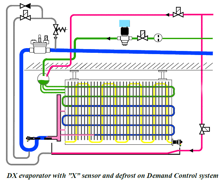
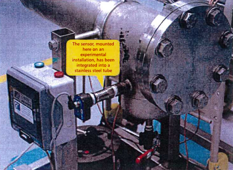
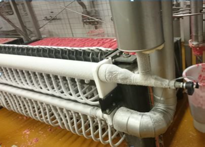
Placing the sensor – at the compressor suction inlet
The sensor can be placed anywhere on the pipeline between the liquid separator and the compressor. It must be placed so that it provides optimal detection on a 2-phased liquid flow (gas/liquid). In this position it detects both the drizzling and the river running in the bottom of the pipe. See the installation guide page. If the sensor is placed near the compressor, it will detect both liquid run-back from the separator and it will detect if condensation forms liquid pockets that are suddenly released from the piping. The disadvantage with this placement is that there is a limited reaction time.

The sensor can be placed either in front of the suction line on the compressor or just after the outlet of the pump separator.
Placing the sensor – at the liquid separator’s outlet
If the sensor is placed at the liquid separator’s outlet, the conditions affecting the reaction time of the compressor are better, but refrigerant condensation in the suction line will not be detected. In this situation, the emergency stop on the compressor should also be engaged. Since the sensor also has analogue output, it is possible to place an intelligent controller in the refrigeration system’s PLC. If a small amount of overflow occurs during operation, a natural reaction would be to double the suction pressure and then slowly step it back down to normal. This way, it is possible to keep the plant running and avoid many starts/stops due to lugging.
![White Paper : Vapor Quality Sensors [Before 2022]](http://www.hbtransducer.com/blog/zb_users/upload/2023/12/202312291703900198460949.jpg)
