Leakage Detection - Detecting CO2 Leakage Into Ammonia
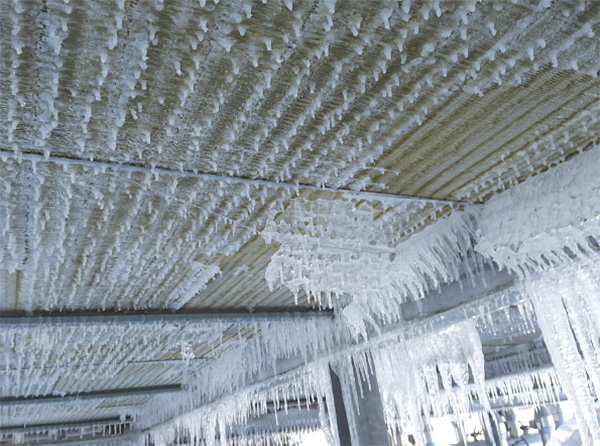
Two different sensors are available for detecting leakage in CO2/ammonia cascade systems and they both react on the formation of ammonia carbamate which is a very corrosive salt that blocks the pipes and compressor. The sensor Detects a leakage quickly because the conductivity increases significantly when ammonia carbamate is formed.
Shell and tube and shell and plate systems
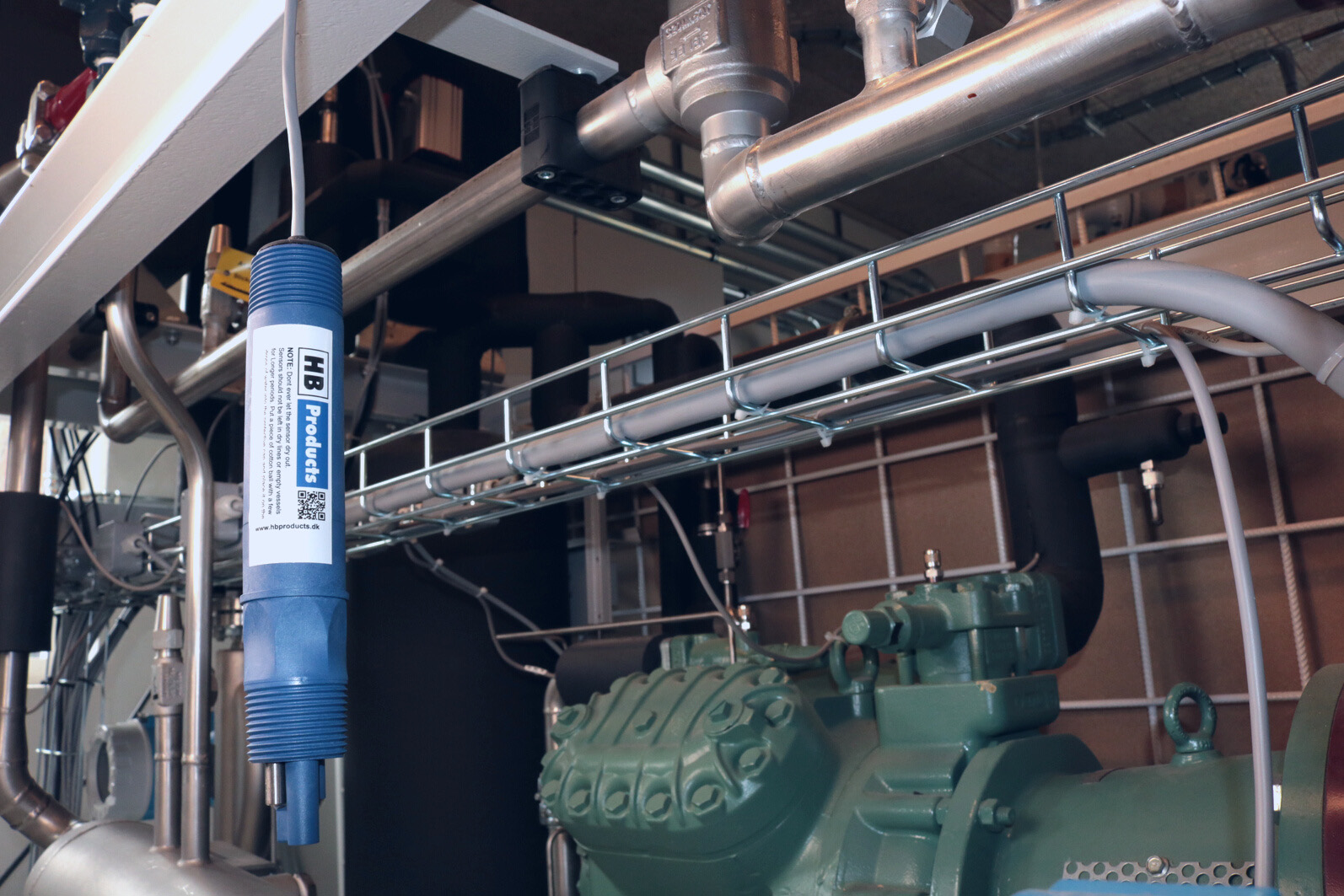
In systems with a shell/vessel type of heat exchanger the HBAC sensor should be mounted in the liquid ammonia at the bottom of the vessel because the ammonium carbamate has a higher density than both oil and ammonia.
The sensor will detect a leakage and provide a warning independently of the location in oil or ammonia. It only reacts on a media with high dielectric constant.
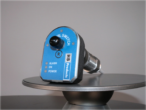
The sensor has both an analog output which can be monitored continuously and a digital alarm output on pin 3 which is activated when the sensor detects ammonia carbamate. The digital alarm output can be configured as both normally open and normally closed.

What happens when an alarm goes off?
The red alarm LED flashes
The digital output on pin 3 changes from ON to OFF or OFF to ON depending on the NO/NC setting
The analog output get higher than 16mA
The sensor can detect whether it is in oil or ammonia, but it requires new settings - please contact HB Products if you like to use this functionality.
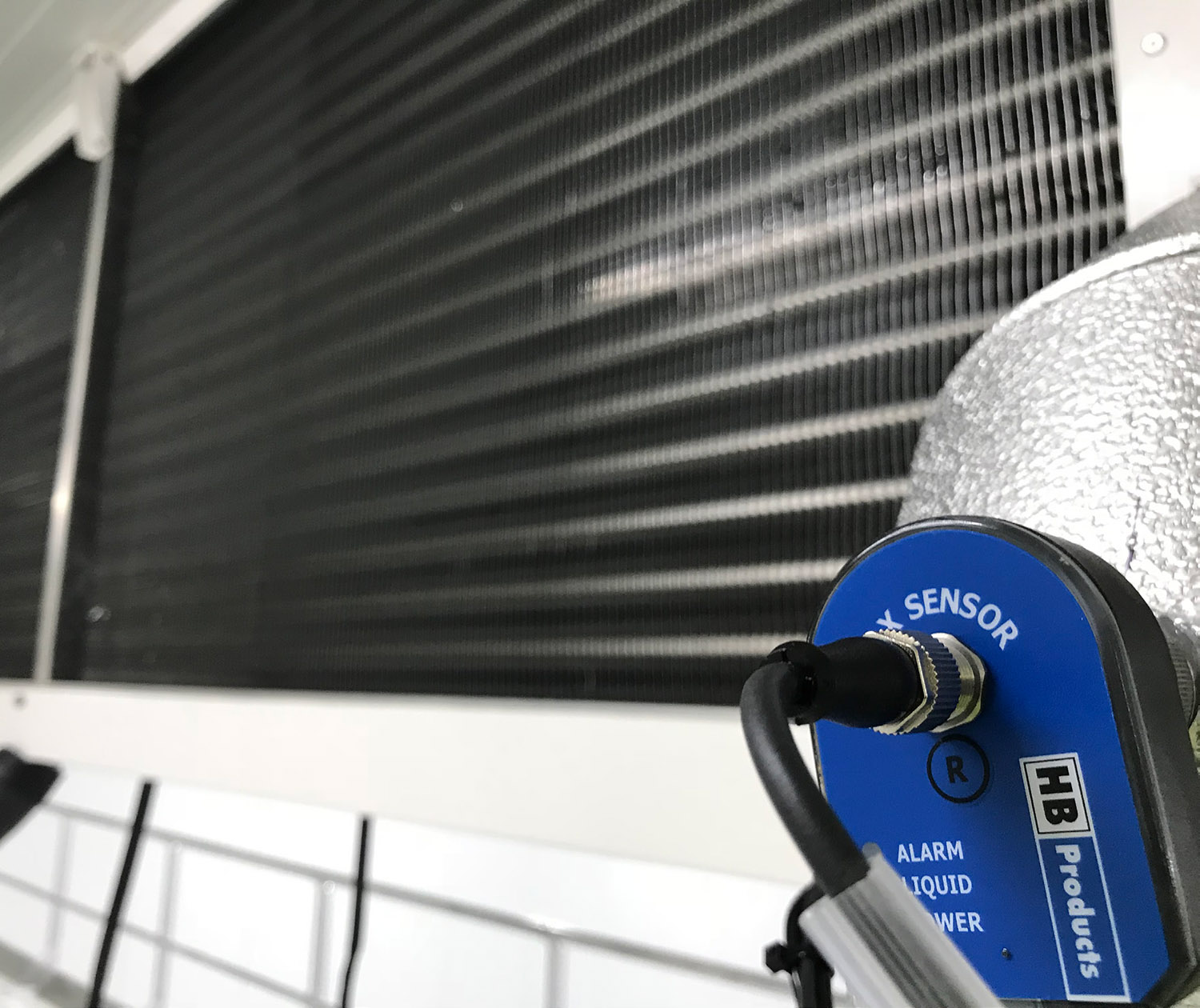
Plate heat exchanger – Use an HBX Vapor Quality Sensor
If you like to detect ammonia carbamate created in a plate heat exchanger the HBX Vapor Quality Sensor is used.

The sensor can either be used only as a leakage sensor or it can work both as a leakage sensor and at the same time control the evaporation process. In all cases the alarm function can be used, and this alarm will provide a digital output on pin 3 for a PLC or a relay.
Setting the alarm
The alarm limit is set to an X value 20 % below the normal operation, which typically will be
X = 0.7 for a DX systems
X = 0.2 for an overfeed system. The alarm settings must be outside the normal operating window to avoid false alarms.
Using the analog output as additional alarm
If the sensor only serves as leakage detector the analog output on pin 4 can also be used as an additional alarm in a PLC - it just requires that the sensor has the right settings. The settings are different from sensor to sensor and whether the sensor operates in a DX or overfeed system.
What happens when an alarm sets off?
The red alarm LED flashes
The digital output on pin 3 change from on to off or off to on depending on the NO/NC setting
The analog output get higher than 12mA (not for sensors controlling the evaporator)
How to check the functionality
If the sensor plays a critical role in your system you should check the functionality regularly. The procedure will be different, depending on your system and what you like to verify.
The HBAC type
Follow these steps to check HBAC when installed in the vessel:
1. Connect the sensor to a PC using a USB/M12 cable. Make sure the HB Tool is installed – you can download it here.
2. Go to the diagnostic tab and read the “Actual measurement in pF” the reading should be in the range 65 to 75 pF when fully submerged in ammonia, and less if it is in oil.
If you need to check the alarm system and the complete activation of the sensor, please follow these steps:
1. Evacuate your system and remove the sensor from the system.
2. Place the sensor in a tall metal cup (minimum 160 mm deep) filled with a salty 1 % NaCl water mixture. Make sure the cup is grounded.
3. Connect the power supply and the sensor should now go into alarm mode when fully submerged.
If you want to avoid removing the sensor from the system you can purchase an additional mechanical unit which then can be connected to the electronic unit and tested in the metal cup.
The HBX type
The HBX sensor is typically difficult to dismantle and verify like the HBAC sensor, but when placed in the evaporator output it is possible to check the functionality continually by monitoring and logging the output. If you like to test the alarm function further, you can purchase a test probe specially designed, so it has a capacitance equal to the capacitance of the sensor when alarm occur. Contact HB-products sales for such a test probe.
If the sensor is used for evaporator control and the control system is operating within the process limits the sensor is operational and there is no need for further verification.
If the sensor is only used for leakage detection it is relevant to monitor the output of the sensor, please follow these steps:
Connect the sensor to a PC using a USB/M12 cable. Make sure the HB Tool is installed – you can download it here.
Go to the diagnostic tab and read the “Actual measurement in pF” the reading should be like this:
For DX systems: The X value should vary between 0.95 and 1, if the value is constantly X = 1.0 you either run with too much superheat or the sensor is faulty
For overfeed systems: The X value should be 1/circulation ratio, there should be some variation around this figure.
For further verification you can purchase the special test probe and move the electronic unit from the mechanical sensor element to the test probe. This should make the system go into alarm mode.
Download The PDF Article: Leakage detection ( pdf, 427 KB )
![White Paper : Vapor Quality Sensors [Before 2022]](http://www.hbtransducer.com/blog/zb_users/upload/2023/12/202312291703900198460949.jpg)