New Refrigerant Quality Measurement and Demand Defrost Methods
Technical Paper :New Refrigerant Quality Measurement and Demand Defrost Methods
Michael Elstroem, BTecMan & MarEng.
Techinal Manager, HB Products A/S Boegekildevej 21, DK-8361 Hasselager Denmark. me@hbproducts.dk
Abstract : New measurement methods make it possible to design energy-efficient Low Charge Evaporator Systems Controlling both the injection of refrigerant according to the Evaporator load and Defrost cycle “demand defrost” while also increasing safety aspect when using natural refrigerants as Ammonia.
Requirements to reduce global warming (GWP) and CO2 emissions lead to a desire to use natural refrigerants. This has initiated numerous new efforts and developments worldwide. Application of new measurement principles and design methods in the refrigeration industry may significantly impact the achievement of lower global electrical energy consumption by realizing reductions of 20 to 40% (Jensen, 2015). At the same time safety may be increased by minimizing the refrigerant amount through “LOW CHARGE SYSTEMS” with a charge reduction factor of 30 to 50 times for Ammonia DX systems (Nelson, 2013). The heat transfer coefficient within the evaporators is highly dependent on the flow pattern, mass flux and the Vapor Quality.
This paper describes a new sensor system for optimizing Evaporator Control including description of the measurement principle for measuring the phase of refrigerant as Vapor Quality with an “X” sensor that measures degree of dryness and a demand defrost sensor measuring ice build-up on the air cooler surface. The paper also provides information about sensor design, laboratory testing, system design, field testing, application, summary and conclusions.
1. INTRODUCTION
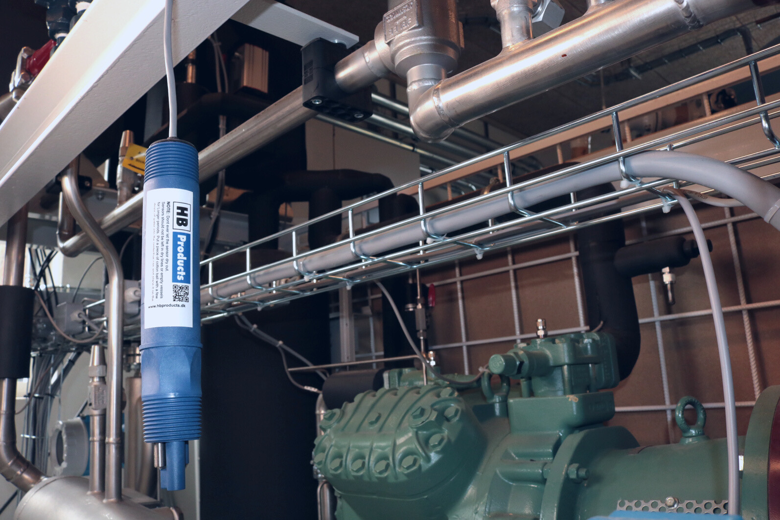
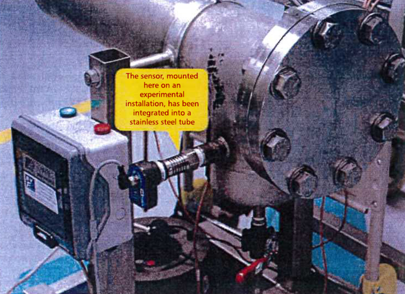
Five years of experience in testing and installation on ammonia systems have proven that an “X”Vapor Quality Sensor mounted in the exit of an evaporator optimizes the entire system and makes it possible to control and limit the amount of refrigerant in the evaporator under all loads by only supplying the refrigerant needed to the evaporator depending on the load. Experience in using the same Vapor Quality Sensor on HFC plant shows that it provides the same benefits of minimizing superheat and optimizing the evaporator efficiency. Further optimization is possible by installing a defrosting sensor on the outside of the air-cooler tubes in the air inlet side, the sensor measures the ice layer thickness and can start defrosting at desired ice layer thickness “Defrost on demand”.
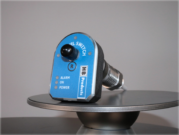
Hot-gas defrost can be optimized by using the "X" sensor for measuring and control draining of condensate hot-gas to ensure that the entire heat exchanger area is utilized optimally and thus minimizing defrosting time. The “X” and Defrost sensor is an optimal solution from an energy performance point of view by optimize the operation and function during both frost and defrost operation, and at the same time increase safety by ensuring that the evaporator tubes is empty for liquid before start and stop hot-gas defrost, this prevent risk of liquid hammering.
2. HOW IT WORKS
The sensor is based on the capacitive measurement principle in which two or more measuringelectrodes/conductors measure the charges and change in electrical field/resistance depending ondifference in the dielectric properties of various media. Hereby the ratio between vapor and liquidamounts is measured instantaneously, i.e., without delay as a Void Fraction measurement.
What is an electrical capacitor?
A capacitor is a component designed to create and hold an electric field, which means that capacitors can store energy. It takes energy to pull electric charges apart and so establish an electric field between the separated conductors. Capacitors are like small batteries.
Capacitance is a measure of how much charge is needed to produce a given potential difference between two separated conductors. In other words, capacitance is defined as the ratio of the amount of charge stored to the resulting voltage difference. The insulating material between the conductors is known as the dielectric. Typical dielectrics used in electronic systems are ceramics, plastics and air.
The measured value is dependent upon the total sensing area and the internal distance between the conductors/electrodes. The ratio of the capacitance measured in pF is then dependent upon the material between the electrodes. Relative permittivity is the factor by which the electric field/charges on the electrodes is changed and named as dielectric constant ε, Refrigerant have ε > 1, some common values are given in the table “ε”DC below.
The dielectric constant (relative permittivity) is a numerical value on a scale of 1 to 100 which relates to the ability of the dielectric material to store an electrostatic charge. The dielectric constant of a material is determined in an actual test Cell. Values for many materials are published on the internet.
Due to the difference between the dielectric constant of gas and liquid in two-phase Vapor-liquid flows, the
measured capacitance between the electrodes depends on the Void Fraction.
Special Considerations:
The dielectric constant of most materials varies with temperature, which affects the capacitance measured by the conductors. Generally materials with a higher dielectric constant are less affected by temperature variation. The temperature effect is usually given in the tables of dielectric constants.
Material buildup: The most devastating effect on the accuracy of capacitive measurements is caused by the buildup of conductive material on the conductor/sensor surface. Non-conductive buildup is not as serious since it only represents a small part of the total capacitance. Oil is non-conductive, metal impurities as dirt is an example of a material that is conductive.
Chemicals may affect the insulating material. The accuracy of the capacitive measurements can be influenced by the absorption of chemicals (refrigerant) into the insulating material causing swelling.
Parameters which influence the flow pattern and have strong impact on heat transfer:
In thermodynamics, Vapor Quality is the mass fraction between vapor and liquid/vapor in a saturated wet mixture; i.e. saturated vapor has a quality of 1.0,
and pure liquid has a quality of 0. Quality “X” can be calculated by dividing
the mass of the vapor by the mass of the total mixture.

The elimination of superheat measurement for evaporator control can be used for reducing the temperature difference “ETD” between the ammonia and air temperature (the plant in Melbourne measured “ETD” down to 2.5K) – especially in case of partial load. This reduces the system energy consumption because the compressors operate with the highest possible suction pressure in all operational situations. It also minimizes the volume of the gas, thus the compressor works less and thereby uses less energy. Compared to HFC , it is possible to increase energy efficiency by 40% with an ammonia DX system. Compared with a liquid overfeed system, energy efficiency is increased by up to 25% with a low charge NH3 system (depending on the system design) (Jensen, 2015) while the refrigerant inventory is reduced by a factor 30 to 50 (Nelson, 2013).

Technical Paper:
Technical Paper New Refrigerant Quality Measurement and Demand Defrost Methods(1.92MB)
![White Paper : Vapor Quality Sensors [Before 2022]](http://www.hbtransducer.com/blog/zb_users/upload/2023/12/202312291703900198460949.jpg)