HBProducts | Demand Defrost
sThe defrost sensor measures the frost layer on the fins and provide a 4-20 mA signal for the PLC or controller. The measurement is used for starting and stopping the defrosting when needed and only when needed.
sThe defrost sensor measures the frost layer on the fins and provide a 4-20 mA signal for the PLC or controller. The measurement is used for starting and stopping the defrosting when needed and only when needed.
Application: Freezer -30°C to 10°C
Product Code: HBDF
Application: Heat pump
Product Code: HBDF-OD
Application: Freezer -30°C to 0°C
Product Code: HBDF-Freezer
Application: Freezer -60°C to 0°C
Product Code: HBDF-LT
Output: 4..20 mA | Measurng of: Ice up to 100 mm
Product Code: HBIB
The energy consumption increases when the evaporator is blocked with ice so the air can’t pass, and the fins are insulated by the ice.
Traditionally, evaporator defrosts are based on a fixed schedule, by basing the defrosting on a real measurement defrost can be done only when needed. This can typically reduce the number of defrosting cycles by 50%.
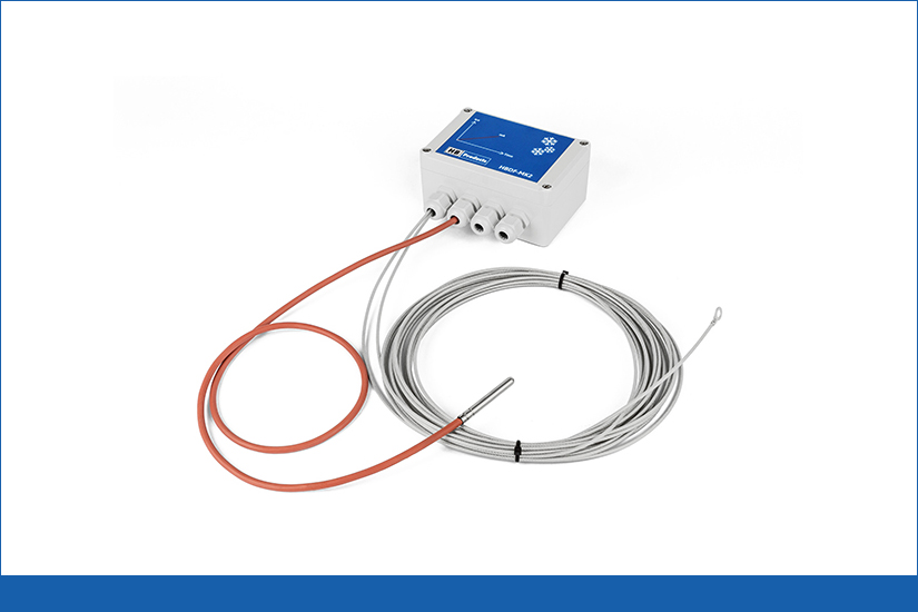
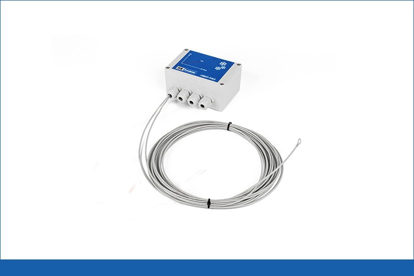
The sensor consists of a control box, a coated steel wire and a temperature sensor for some of the versions.
To determine frost accumulation levels, the sensor measures a change in capacitance between a coated steel wire and the evaporator fins.
The defrost sensor is based on the capacitive measuring principle, in which an insulated steel wire acts as one conductor and the evaporator fins act as the second conductor. The sensor measures the ice thickness between the fins. The output is either a 4-20mA analog output or a more advanced digital output to the control system. The digital output can be used directly to control the defrosting and includes a temperature sensor which senses when defrost is completed.
The sensor can be installed in less than an hour, on both new and old evaporators. It can even be installed when the system is in operation, hence shutdown is not necessary. The electronic part is mounted on the evaporator’s frame by using 2-4 screws. The mechanical part consists of a thin coated wire, which is mounted between the fins of the evaporator where ice built up. The wire is either mounted using standard nylon cable ties or put around the pipes. The HBDF sensor is available in 3 versions, with a 10-, 20-, and 30-meter wire.
After the installation, the sensor should be calibrated/configured to the evaporator by using the HB-TOOL (PC-based software tool), which can be downloaded from our website.
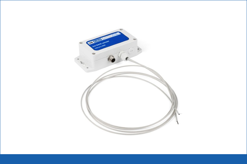
Ice Bank Sensor
The sensor can measure how much water is turned into ice in an ice bank. The measurement is done between two coated steel wires placed in the water. The steel wires are typically attached to the cooling pipes.
Downloads Related Brochure
For Hazardous media : Ammonia , CO2(Carbon Dioxide) , HFC /HFO ,Oil , Defrost and so on.
HBProducts Include : Vapor Quality Sensors , Liquid Level Switches , Liquid Level Sensors , Safety/Leakage Detection , Demand Defrost , Pressure & Temperature Sensors , Motorized Control Valves , IECEx & ATEX Sensors , Miscellaneous etc.